Here are some notes on the framing/benchwork for the Sandy Lake & Northern. Since I have moved a lot, I designed the layout to be easy to disassemble. This had the additional benefit of making each piece small and easy for one person to handle.
The basic approach is "modules" of the appropriate size. My Railroad room is roughly "z shaped". There are two framing style. In the first, I was experimenting with I-beams made from pine and thin birch plywood. The second was made from clear pine 1x4 stock (ripped down from 1x6). The frames were covered by 1 1/2" or 2" styrofoam insulation board. What surprised me was that the I-beam modules were not sigificantly lighter than the more conventionally wood framed modules. In part this is due to using heavy 3/4" oak plywood for corner gussets, which are probably not needed. According to my bathroom scale, the modules averaged 22 lbs. They were easy for me to carry from the garage, down the stairs and into the train room.
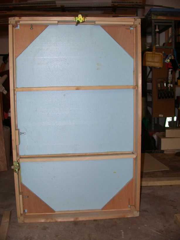
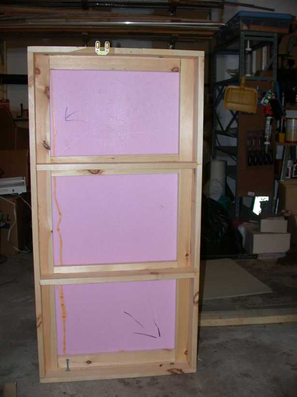
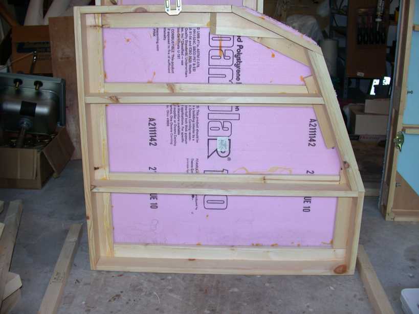
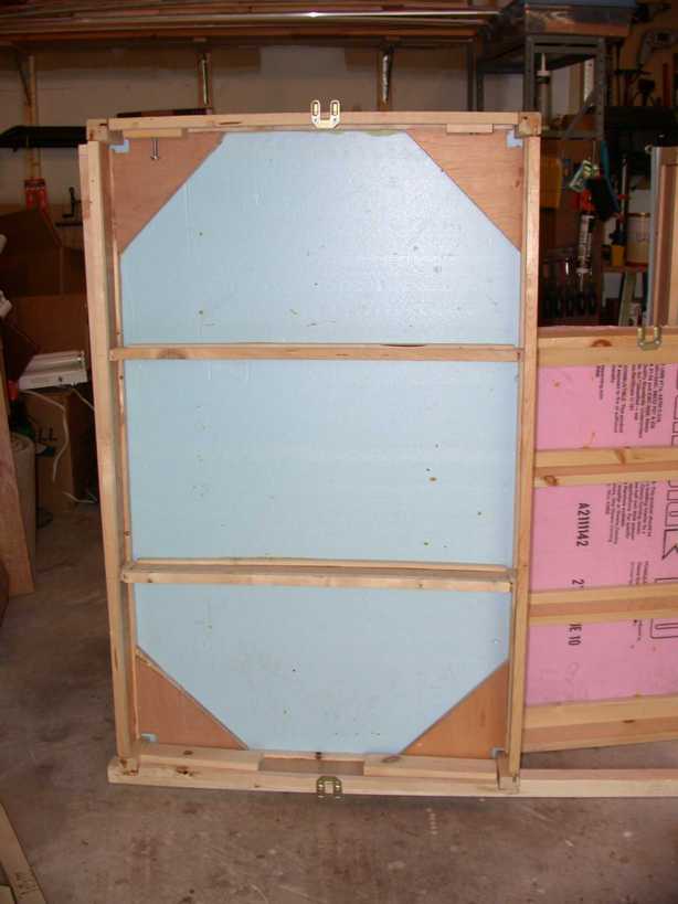
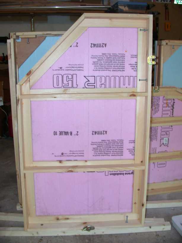
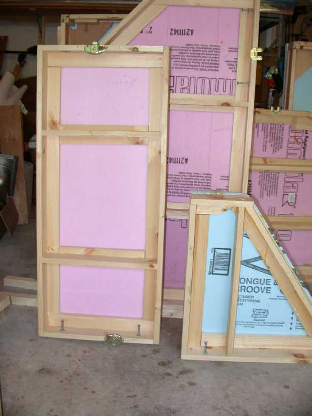
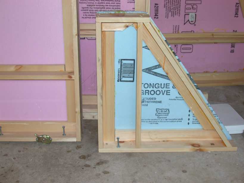
Anyway, the frames are about 24" to 36" wide, and 36" to 48" long. The conventional wood frames consist of 1x4 verticals with 1x2 horizontals to form an l-beam around the edge (the corners of the L facing inward. The center joists are on roughly 16" centers, with a 1x2" on top (making a T shape). Everything is glued and screwed. The I-beam modules do not have the L shaped framing. Instead, there are 6" triangular gussets along each corner. The Styrofoam insulation is glued using waterproof yellow wood glue, weighed down until the glue melts.
In terms of construction, the #1 tool here is a table saw with a rip blade. If you plan to do something like this, invest in a good quality rip sawblade ($35 or so.) Combination blades do NOT work as well. I buy 1x6x10' and rip them into 3.5"/1.5" pieces. I use a mitre (chop) saw for most of the angles. The angle corners were a bit of a challenge to cut; in some cases I used 2 pieces to provide reinforcing for the screws.
Each module is connected by two 1/4-40 bolts, screwed into T nuts on the other side. I alternated the T nut, so each module side has one bolt head and one T nut. I also bought some clamps like you find on dining table leaves. These turn out to be helpful to align things during installation, but they probably do not add a lot of extra stability once the bolts are screwed in. The intent is not to make a truly portable layout, but one that can be moved once or twice, if necessary.
The first 7 photos (dscn01918-dscn0924) show the modules. It's a good idea to take photos of the framing, in case you wonder where a joist is located...
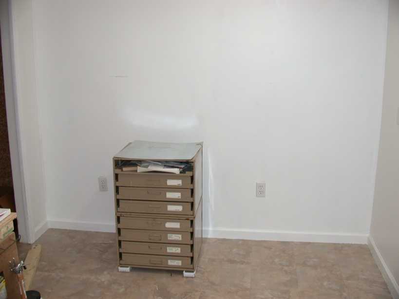
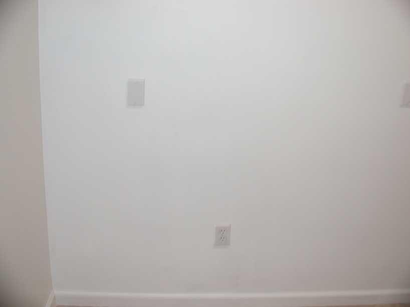
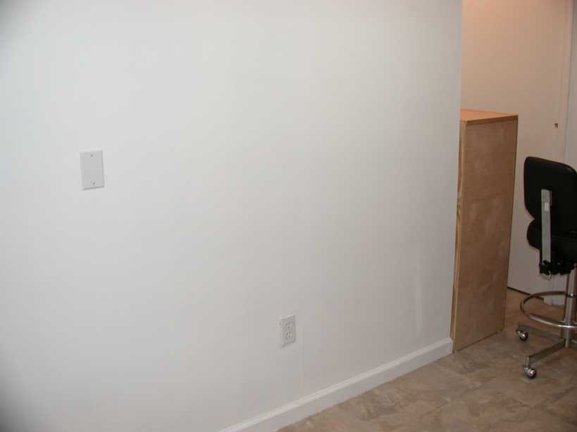
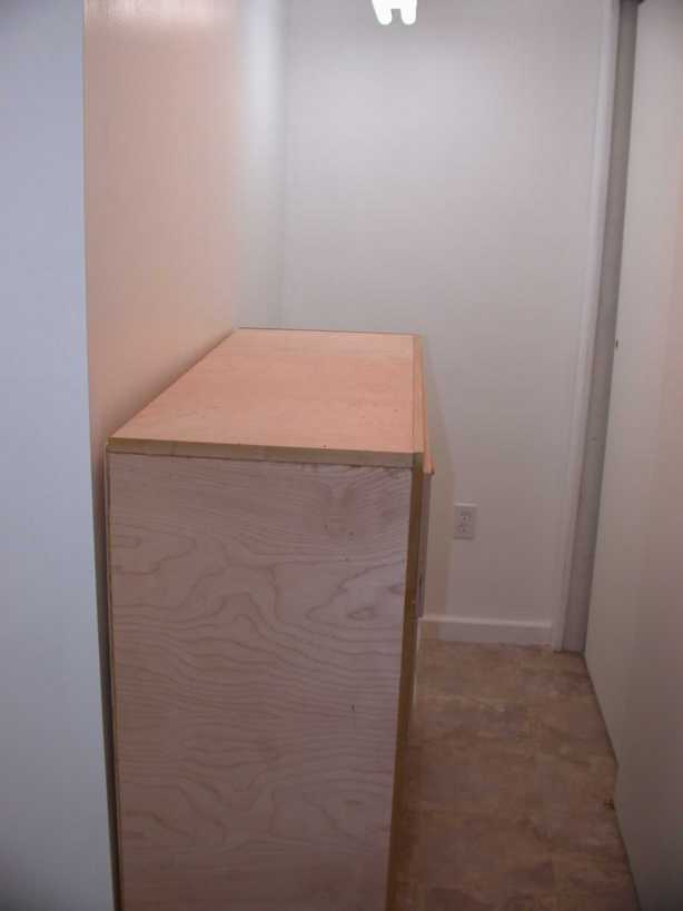
The last photo above and the next 3 photos show the room where I'm installing the modules. Everything is emptied out, except for my parts drawer, which is too heavy to move and a cabinet that I was too lazy to move.
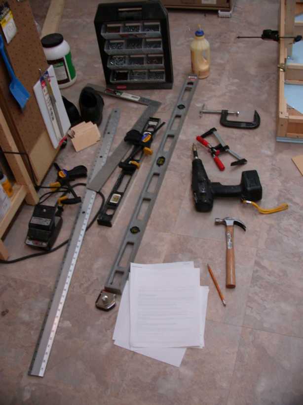
The last photo in the next row (dscn0925.jpg) shows the tools I used to install the frames.My brother, a professional carpenter, says "You can never have too many clamps." For this project, particularly doing it alone, you need several one-handed clamps and a cordless drill with a swappable screw pilot/screwdriver. When we lived in Canada, I discovered Robertson square-drive screws. Now I use nothing else. One advantage is that you can put the screw on the drive and it won't fall off! Two levels (48" and 24"), screws, pencil and paper, framing square, more clamps, hammer (to persuade both bolts and even a module into line...) and screwdrivers complete the toolset.
Back in the garage, I cut another couple of 2x6 in half, and glued them together to make L-girder. The L-girder will be screwed into the wall, and the modules will rest on top of them. Legs in the front will hold up the front of the modules.
 dscn0926.jpg (2048x1536) 1.0MB |
 dscn0927.jpg (2048x1536) 1.1MB |
 dscn0928.jpg (2048x1536) 1023.9KB |
 dscn0929.jpg (2048x1536) 912.2KB |
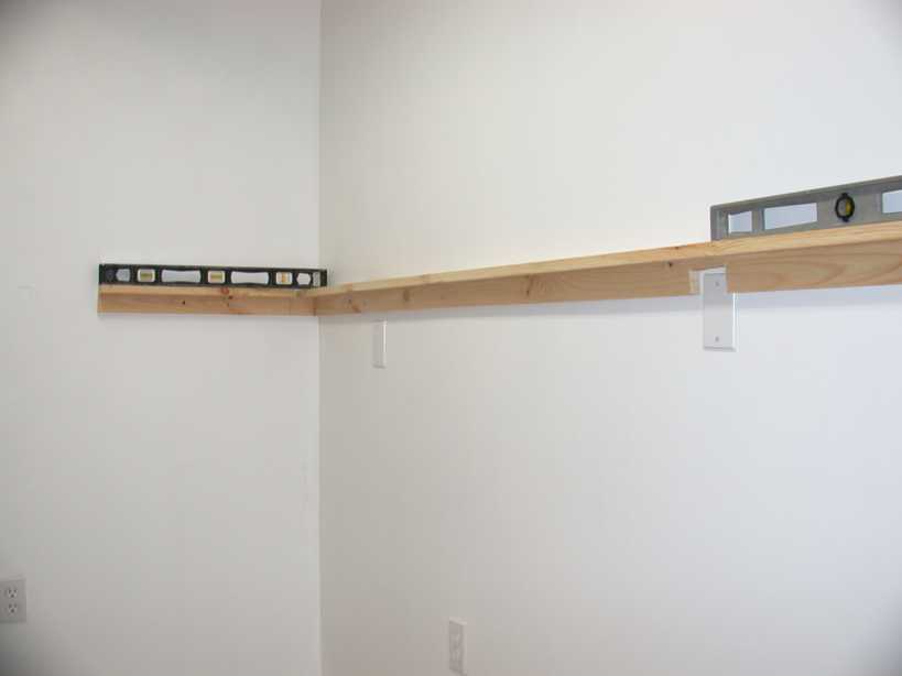
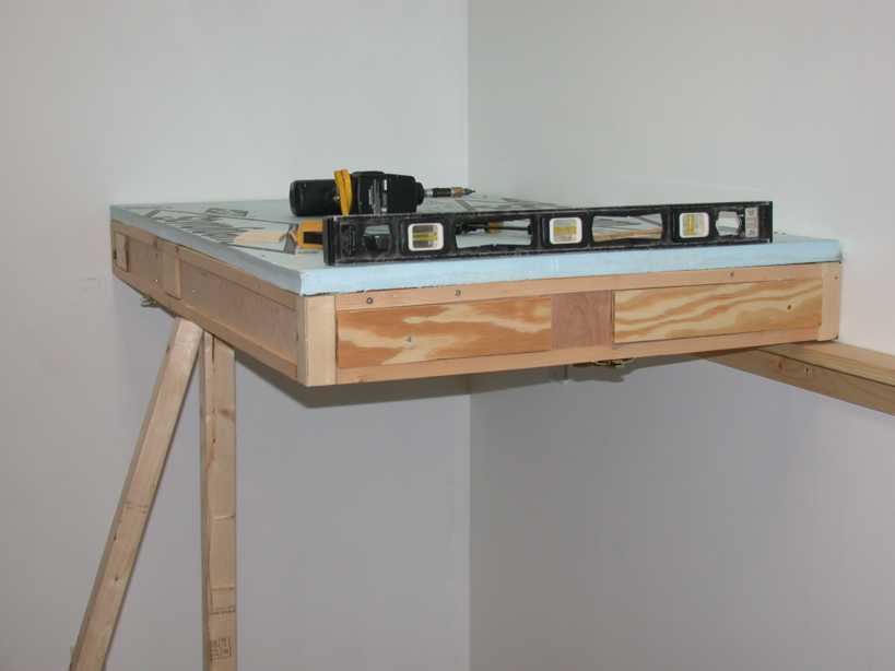
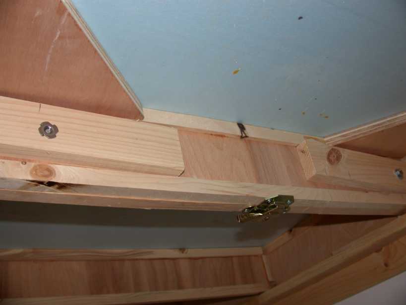
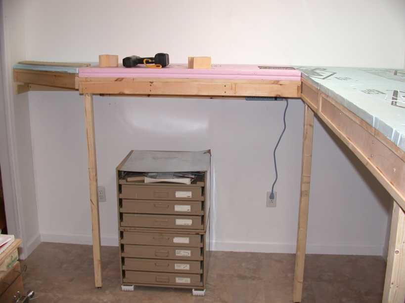
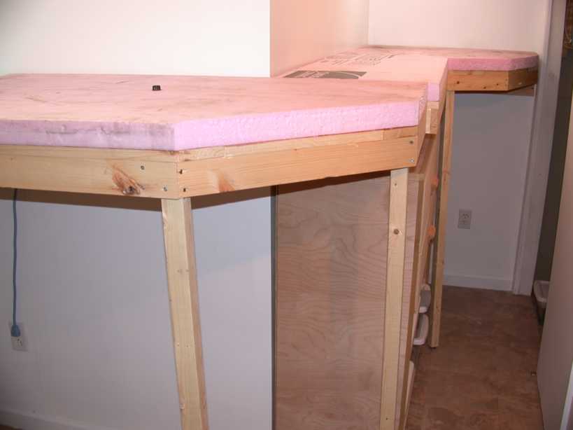
Dscn0930 shows the L girder screwed into the wall, and dscn0931 shows the first module in place. Note the clamp holding the leg up. Once everything is level (using shims in the back where necessary), I screw the leg onto the frame. Dscn0932 shows the second module (the second of the two I-beam modules) in place. Dscn0933 is a shot from underneath. You can see the corner brackets, the extra 1x4 I added to reinforce the I-beam where the bolts pass through, and in the lower middle, the table leaf clamp. At the near left is a bolt from the other side to the T nut, and at the very far right is the bolt head passing through to the T nut on the other side. These are tightened via a socket wrench.
 dscn0930.jpg (2048x1536) 1.1MB |
 dscn0931.jpg (2048x1536) 1.1MB |
 dscn0932.jpg (2048x1536) 1.0MB |
 dscn0933.jpg (2048x1536) 985.5KB |
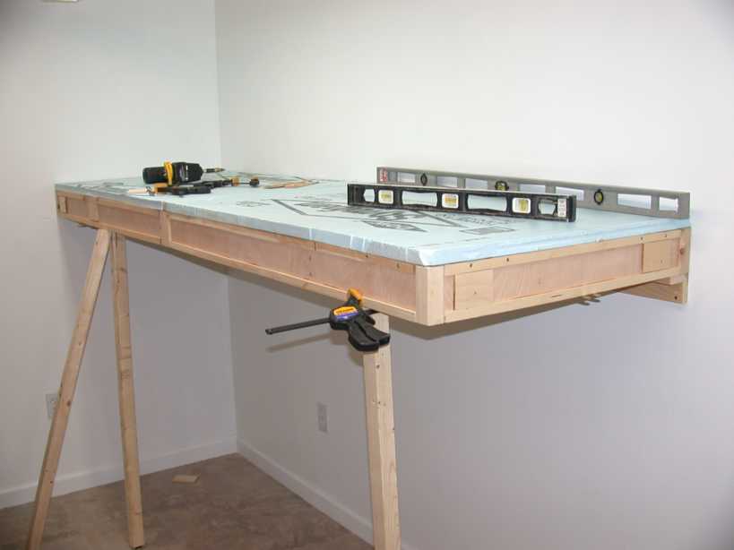
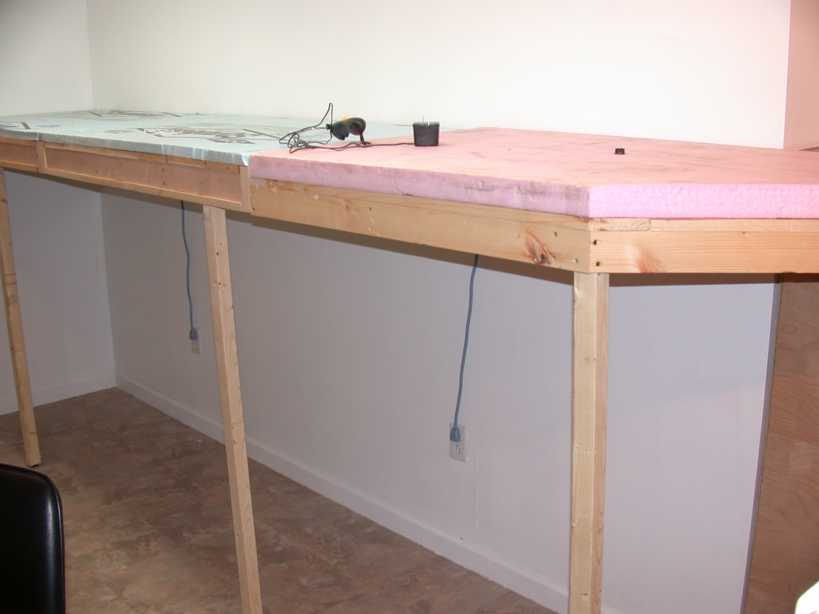
Several hours later, everything is in place. I'd like to admit that it all went perfectly, but the walls aren't square, and I had to redrill and reposition bolts between two of the units. I have bookcases to install underneath the benchwork, and I moved the legs to locations that were most convenient to access the books. Note the plugs in the walls, particularly in dscn0936. These are for cheap power strips that are fastened to the benchwork. Once the bookcases are in place, the standard-height plugs will not be accessable, and like clamps, you can't have too many plugs near the benchwork.
 dscn0934.jpg (2048x1536) 1.0MB |
 dscn0935.jpg (2048x1536) 1013.4KB |
 dscn0936.jpg (2048x1536) 1.1MB |
Here's a plan of the benchwork, with sizes and an indication of the
module boundaries:
Time to install all 7 modules was about 8 hours. It probably took me another 16 hours to construct the frames, including the I-beam modules. They took much more time than they were worth. Everything is very tight and mostly level (there are a couple of uneven places, due in part to differences in height between the L-girder and I-beam modules.)
I plan to add/remove styrofoam to get the geology in place, and then glue homasote subroadbed to the styrofoam. Then I'll drill through the homasote/styrofoam layers for the track wiring feeders, using a nice long drill.
Stay tuned for the next installment.